Quantcast
Channel: InMoov
Viewing all 75 articles
Browse latest View live

InMoov's brain at work

$
0
0
In my previous post, I was talking about Myrobotlab for the brain, and I want to explain a little bit more of what's going on. I have been searching for an easy to use software in order to control InMoov's servos. My goal was to be as open source as I could, so keeping my Arduino boards, and not to go into closed systems. Of course the choice is yours once you are building your robot. Through my search I read on different forums about Myrobotlab and this guy ,GroG, was the one who ruled it.

I had tried to use the software a few times, trying to figure stuff on my own, but I finally decided to contact him. And boy, what a help! The Gui still remains opaque to me, but since I had been fooling around with Arduino scripts since January, I was ready to jump into Python scripts. At my very low level of knowledge of course. GroG has been helping to figure out many problems I had with scripts but mainly has been working on creating a special service in his software for InMoov.

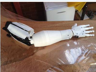
This means if you have printed let say the hand and forarm and set servos inside and you are looking for a way to control it, with that service you can. It allows you to test your servo's movements with sliders. If you have a microphone with your PC you can give voice commands to your servos. OpenCV should be easily installed when you install the software, that will allow you to control with it's own vision your robot.
There is Tutorials, and maybe some more coming up for easier understanding.

For the software to take control of the servos through the Arduino board:

-First download Myrobotlab. Here Get the last one on the bottom of the list.
-Unzip into your hard drive C:\
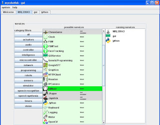
-Open the folder Myrobotlab in C:\ and double click on myrobotlab.bat
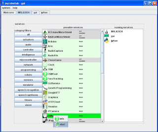
-Right click on InMoov's service and click "install"
-Start the Arduino service by right clicking on it and give it a name, for exemple: arduino1

-Choose in the Arduino tab, the type of board you have and which serial port it is connected to.
-Then upload the script on to your board. (It seems that sometimes it doesn't work through the GUI, in that case copy click the script and upload it directly on your board using the Arduino.exe)

-Start the service InMoov by right clicking on it and give it a name, for exemple: inmoov1

 -At this point the GUI will load all the servos and will attach them to your board.
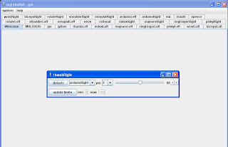
If you click on the "thumbRight" tab you will have access to the slider of the thumb servo.
Notice all the servos and two arduinos are now available in the tab bar.
This is for both arms, right and left + the head.
Ear tab is for giving voice commands, Mouth is for the robot to talk back.
OpenCV is if you have a camera set in the head. (Although those STL parts are not ready for downloads yet)
 
So now you have the base, it's up to you to play around, discover and there will be more to come according to GroG.

Following the tutorials might help you to go further.

Hope you have fun!


Power supply + robot head printed

$
0
0
Being stucked on a problem is never fun, and this is what's going on right now. 

I had bought a fancy power supply thinking "This is The One" that will power the whole robot, but I guess I was wrong. You see since the beginning of this project I had been using a very small power supply DC6V3A I had laying around in my workshop. But by adding more and more servos to it, I came to realize it was not enough anymore to power up the 22 servos of InMoov. During the initialization, each servo seems to draw about 2 Amps. I guess I was just lucky with my small supply to already be able to run the arm and not fry it instantly.

So I got "The One" after searching quite a bit on the net, it seemed to have the amps I required and the 6V I needed for the servos I'm using. 
This thing was expensive, but it was sold by the same kind of shop that sales servos for hobbiest so I thought it must be compliant. I'm no electrician, I do all those things by guessing...

Okay, I received the Power supply, I was excited because I was going to finally get the whole robot to move. First thing I did was to test with a simple Arduino sketch with only one servo. It worked perfect!
Since I had the right arm connected to the Arduino Uno, I plugged it and ran the simple Arduino sketch again. Perfect!!

At that point I had to think of making a small pcb board to connect all my servos and my two Arduino board all to that single power supply.


Once again I ran a simple test with my two Aduino boards and only 8 servos attached. It went perfect again!
Boy, was I getting excited!
So I went straight forward and plugged every thing together, 22 servos, 2 Aduinos, 1 power supply. I had used only one side of the output of the power supply, instead of both, which can each deliver 20Amps and I think here lays my mistake.
I ran the simple sketch which is only moving all the servos from, let say, 0 to 30 position. Some of the servos were already at 0 position. Then they all had to move to their new positions, here started some strange behaviours. Some of the servos were jittering (shaking), and the movements of the robot became erratic.
I unplugged everything, rechecked all my connections, everything seemed okay.

At that point I thought, I must have plugged or touched something that did that strange acting, and decided to go on.

So excited I was , it was the time to get InMoov controlled through Myrobotlab.
Here starts the initialization, and I get this same kind of strange behaviour, all servos buzzing, erratical moves.
Then all of a sudden one of the arm starts to twist way further then what it is supposed to do!!
WOW! I unplugged everything...
I ran the same test again, but this time everything went off at once, no more power. The power supply is protected against short circuit, thermal heat, and overload drawing.
I checked all the connections one by one again, nothing was wrong.
What was the problem, so I restarted with my first initial test, 1 Arduino, 1 servo, simple sketch, it was not perfect at all anymore. It was acting totally erraticaly...! 
And since then of on.
There must be something damaged in the power supply, strangely if I use it with another device, like a little DC motor, it works normal.

So, end of the story, back in search on the net. I read on this page what I hadn't found before about switching power supplies with servos.
Now, I have ordered three batteries with a small charger. They were very cheap when I passed my order, 8 euros per battery. I think that will do for now, I also had found some Lipo batteries but they are rather expensive.
I really would rather a power supply, because I just don't want to have doubts about the power or wait for charging time. I need a DC 6V 44Amps or more, no swithching, with a 250V input.
Would be great if someone has an idea. Any suggestion is welcomed, please post in the comments.


In the meanwhile I have been designing and printing more parts for the head. I also redesigned the top of the front torso, the other was going too high in the middle, and it bothered me because it wasn't taking a human shape structure.
The jaw has it's own servo motor mounted and can be actionned. I still need to test the microphones in the ear circus amplifiers, but this is pure creating guessing. I have no idea if it's going to help InMoov to hear better the voice commands. But hey, why not try something different since I can print and design what ever I want!
3D printed robot head inmoov
Robot head sideway without ear

3D printed robotic head inmoov
InMoov has ears and jaw attached

InMoov robot new neck and yes
Changements have been done on the torso structures of InMoov


Shoulder InMoov for New Year, 3d print it!

$
0
0
Happy New Year to all of you crazy robot fan and builders!
I have a little present for you ready to download. You should be abble to build the shoulder with succes if you follow the tutorial I am going to post in the Assembly Help tab.

I know some of you have been waiting, but I had to redesign and reprint this a few times before to finally get it the way I like it. My initial design and prints didn't have enough DOF, and my second design was too large to stay in a human size range. I tried to use parts of the bicep, but came to realize there was to much pressure/torque on the worm gear, so that also had to be redesigned.
initial design shoulder 3d print
This was the initial design of the shoulders

Redesigned torso DOF 3d print
Then I redesigned the whole thing to get more DOF

3d printed robot
Final result of the torso with shoulders


Of course it could be much more improved but I don't have enough time and money for to do that. For exemple, the printed screw threads could be replaced with linear actuators, making it more accurate and strong. But I try to manage my wallet for this project, and I know a lot of you are in the same kind of position. So if you've got a thick wallet, you can replace those parts fairly easily. I have made the space for it and added attachment holes for to be adaptive. The others with a smaller budget can print and play, if it breaks, well, reprint. Or get them printed by Shapeways in stainless steel for a reasonable price.
inmoov screw 3d print
These are some of the broken and rejected prints I didn't throw away.


But be reassured, I've had these parts on for several weeks now and I have been making them run already quite a few hours, sometimes mistreating them badly, and they are holding. The main breakage I had, were during the implementation of the servos speeds and positions feedback, plus a problem with my power supply, which would make my servos act erratical. If they go further then the limits, they break.

Anyway, like I say following the tutorial should make it easy to construct.

I also need  to upload the torso because the tuto concerns it too. My problem is that I'm not finished with it.
You see I need to think of the vertebra attachments to the torso and that might change a bit still.
We will see...


Voice Commands to InMoov

$
0
0
Mmmmh, I felt like making a clean video of the recent progress.


Torso for InMoov on Cubehero

$
0
0
Hi all,
The torso parts, which allows you to make the junction between the two shoulders and the neck, are uploaded on Cubehero for the moment.
I'm trying to see how that works.

Of course for now the site doesn't look as fancy, compared to Thingiverse, and has some problems to be solved. I can't remove a part that was uploaded by mistake. (It's the one with no thingiview image)
But the guy that runs it is very responsive.

https://cubehero.com/physibles/hairygael/Torso_for_Robot_InMoov

For the building of those parts, check the Tab "Assembly help", it is explained with the shoulders construction. 

When I will have a bit of time I will add some sketchs.

My troubles with power supply are completly gone since I use the batteries. Remember in a previous post, I had jittering servos which would move erraticaly. 
No more of that, I can really focus on the next parts. 
The good news about battery powering, is that it makes InMoov independant for the days he is going to walk around.( Well if he ever walks around...)
One battery is enough to power all the servos, I had bought three, so I'm using all three.
They are very cheap, I found them on a special offer for 8 euros each.

This is great! I found it in my street, someone had dumped a desk chair with wheels, although it is forbidden to dump in the streets.
At least it made a happy finder.
I removed the seat, added a metal tube I had laying in the workshop. It's a super stand for InMoov until he gets his own wheels or feet.

Stand Holder for Torso

$
0
0
This thing was made for my previous torso and someone on the forum requested it for download.
Unfortunatly the torso has been redesigned since then. 
So tonight I pulled myself on the front of the screen, launched Blender and modeled this new part.
Never tried it though, so use it carefully.
It's the green part on the picture, handy stuff, you can now set InMoov on a broomstick.
Ahh, I wish it could already clean up my shop!!

Stand HolderV2 


InMoov Vision Tracking

$
0
0
Last night I made a test after Grog from MyrobotLab has been improving the service tracking for InMoov.
It works pretty well out of the box, I am always amazed how Grog can do those modifications. The movements are rather smooth. If I move the object too fast, InMoov loses the track, so there is a bit of tweaking to do, but there is solutions.
The movement of the head uses only two servos for now, up/down, left/right. There is another servo (HK15298) for to actuate the jaw, but it isn't actif yet. Then two small servos (XGD-11HMB) will be used for to actuate the eyes/camera. I haven't tried these small servos yet, but they can actuate 3kg at 6V, it should be enough. It means later, four servos will be using PID controlled for the vision tracking. 
We should get further very soon I think.


The Replicant

$
0
0
Talking about replication, this one striked me!
This was posted on Here by Jhack.

Printing parts

$
0
0
Like I said on the forum two weeks ago, after the request of builders without printers, I contacted a Printing service which I work with sometimes, I knew their prices would be high...
So, I finally got prices from them. The news isn't so great.
Prices are too high to my taste. Way too high.You might as well buy yourself a printer and start printing, you would be better off. The two arms + torso comes in a range of 3000 euros.

The goal of InMoov is to be built at a reasonable price for most DIYers. 
While printing on your own machine there is the cost of electricity and materials of course. Time consuming doesn't cost you if you do this for the fun (that's the way I see it), but a printing service takes that in consideration and the price goes way up.

Now I'm up with another option, but I still need to gather more details about it, because it is a big step.
We will see in a few weeks if this new plan is viable. 

In the meantime, I started to work on a leg for the fun.


Eye Mechanism

$
0
0
Funny how a little mechanism like this can be difficult to create. It is mainly due to the space where it all has to fit.Although I used small XGD-11HMB servos, they still appear big in there. 
I had done a first mechanism, but every part were just too fragile and flexible. 
So okay, I decided to review it all and turn the bottom servo in another position to get it in there with extra thickness in all the plastic parts.

It is still a bit wobbly.

There is a space for a third servo on the second eye, if one wants to have eyes that wouldn't move simultaneously, Brrr scary freak.

I dismantled the rubber part of my Hercule HD camera and kept only the hard plastic angle which contains the camera. I had previously extracted the microphone and added extra length on the wires, in order to have the microphone in the ears. As you probably have read in some earlier post, sound is a difficult part, which I tend to put further in the future, when I really get extra info. For now a simple bluetooth head set microphone does the trick, between me, the PC and InMoov.

My Hercule HD camera is hot glued on the template support where it belongs on the eye mechanism. On the other template, I could set another camera. But for now, I just did two photocopy papers glued on the mobile template and on the Hercule camera. It isn't fancy, but having only one eye, made him look scary, and I couldn't leave the poor guy like that.

Now, I need to plug that and try to see what happens! 
Isn't that fun!
 
InMoov eye mechanism, inside view
InMoov eye mechanism, side view
InMoov eye mechanism, front view
InMoov eye mechanism, front view. You can see here the jaw mechanism. 


InMoov makes the front cover.

$
0
0
A few months ago I was asked by an American set designer, if I would let them use InMoov hand for to make the front cover of The Atlantic magazine.
Attribution is to be expected inside the magazine. Behing abroad, I have not the chance to buy it for to check it out.

Looking at the result, they did a good job on the finishing touch. If I remember correctly, it was printed in PLA with a 0.3mm thickness. They did a finishing coating with paint, but I would guess they had to use a primer with a good sending job.

Here is the article of CNN, which came out a few weeks ago.


Photo Bart Cook

Photo Bart Cook

InMoov gets surprised!

$
0
0
When I said to my wife, Grog (MyRobotLab) and I have decided it was time to start teaching InMoov, and for that matter I should be looking for colorful objects, she started to become sneaky.

Everytime I was coming in our room she was hidding stuff, or it seemed so.

Tonight the mystery was revealed!
InMoov had is own little toy robot!

Isn't that great, I had to post it. I think it's so cute that InMoov is going to learn very fast how to grab it.

I love the eyes and hook on the head. 
 
Too bad it can't be printed, as I'm sure many of you would like to have it for further test on InMoov or just to have with you during your hard moments of life.


InMoov's little toy front

InMoov's little toy side

InMoov's little toy close up

Neck for InMoov

$
0
0
You can now download the neck with the mechanism that makes the head tilt and pan. 
Get it on Cubehero.
Okay, I guess this is going to be like this. The head contains many parts, so I divised in different sections.
Neck
Skull
Ear
Jaw
Eyes 
There is a part of the skull that is necessary for to do the final mounting of the neck mechanism with servos, it is situated at the rear of the head. I made a piece called "temporary", which you will withdraw once I upload the skull.
I have to make the step by step of the neck, pictures are done, but I need to write the text.
Hope you enjoy it.


Jaw Mechanism

$
0
0
Jaw mechanism is uploaded on Thingiverse.

I have done the complete step by step for the assembly of the neck and jaw. This should get you going.
Check the "Assembly help" tab.

There might be some stuff to modify but it works in my InMoov robot like this for now, and I'm not going to review it all again so you might as well try it like this.
Remember if you decide to modify some parts, there is the eye mechanism, still to come in there.

I hope you have fun building this, sometimes I which I was you guys. What took me a month to create, you just print it and put it together. I'm getting a bit jealous...

Please post your pictures on Thingiverse otherwise I don't keep posting parts!

Sometimes I find people building InMoov, posting pictures on their own blog or site and making modifications and not sharing their work. Not even attributing the parts to InMoov.


This "was" the exemple of what I meant. What do you think about that?
At the time I put this link their post has been modified. 

So thanks to them.
I hope, we hope, we all hope they will put their derivatives files for download.  

Okay, Gael calm down. 

Giving is the best gift you can get.


Simpler Servo Bed

$
0
0
Well, I got bad news for those who bought the HK15298 servos for the forarms. It seems these digital servos have a restricted rotation from 0 to 90° which doesn't let the fingers do their complet movement.
There is search going on at the moment to see if we could reprogram them to get a rotation of 0 to 145°, but it won't be an easy thing, I think.

So if you are about to buy these servos, try to get some others with a 0 to 180° rotation like the analog MG995 I had at first.

This has lead me to design another bracket system.

As it was in my previous version the servos were set sideways, and we could have a total of 5 servos.


The space between the bottom actuator and the robpart was really small


I wanted to create some printed actuator rings with a bigger diameter which would allow restricted servo rotation to get more pulling developpement. So I turned all the servos up,  this way I get more space and actually it all comes out more fonctionnal. I remember when I first designed the forarm brackets, how much time it took me to create it. It was insane.
This went actually pretty fast.


 I have uploaded it on Thingiverse.
You can get here.
You don't need to reprint the "robparts", it can just fit in. You only need to remove two little parts with a plier and it all should go nicely. Fixing the fishing braid will be an easy task, done with a few nots.
The nice thing about this, is that we can have an extra servo in the forarm now. That's a total of 6 servos. With a bit of redesign we could even have 7 servos in there.
We can actuate the thumb with this derivative or create something to move up and down the wrist.
I haven' t tried to print it yet, since I don't need it,  but I think it should be fine.
The assembly is pretty straight forward.
Have fun!


Easter head!

$
0
0
It's Easter and the bells brought you something cool!

Okay, it took me a while to release my robot's face, but understand me it isn't easy to just give away.
You guys better be very gentle with him because I will have eyes and ears every where.


So parts are available on Thingiverse and Cubehero.
I  dispatched them just to protect the Open Source goal of it. I think assembling should be pretty easy to figure out. There is parts that needs to be glued but for the rest it is all assembled with screws, this is mostly for to access the components and mechanism inside the head. 
The eye mechanism is ready but I wait for a little servo to see how it reacts with  stereo movements.

Thanks to Grog, Myrobotlab keeps improving and it seems like the Cortex service is going to be pretty amazing. Added to InMoov service we should get memory. Grog said, "I've been mostly busy trying to make meaningful Memory . Memory in the sense of abstract ideas, objects and relations and a way to visualize them.  It's been challenging but I think I'm finally done with most of the structures and am starting to work on the visualization of memory."

Beside these crazy days of work I just went through, I wanted to find a solution concerning the restriction movements of the HK15298 servos.
 While trying to assemble some junk parts of InMoov to create a simple device for testing a servo connected to one finger, I got an idea.

Hey! but this is what is needed for the beginners, a simple kit which has a finger, a servo, and an Arduino.

inmoov finger starter
The black printed finger is one of the junks I had in my box, very low res print...

This is going to be fun, if you never tried an Arduino and a servo together, we are, Grog, Chris and I, going to make things very simple for you to learn.
First a tuto for to assemble and print this baby InMoov and then a video tuto on how to start MRL in a very simple way to start playing with this.
Grog is going to create a service called InMoov Starter and hopefully it should be pretty easy to make it all happen.

Once you understand how to control this toy, you should be ready, mentaly, to build the complete robot...(Mmmh maybe not, we will see) 

Anyway you can get it here


Iphone controls InMoov

$
0
0
Luckily I just got an Iphone. 
About a year ago when I was working on how to configure my PC to control the arm with a keyboard, I was getting help from Zack through the Net. Back then he said, if I had an Iphone I could certainly control the servos with an Iphone. Unfortunatly I wasn't possessing one.

A week ago, I finally got one and a few days later a new InMoov builder posted a video on Youtube which was actually exactly what Zack had been talking about.
Brancante, the new builder, was kind enough to post a simple tutorial on the forum, which I followed and adapted to a whole arm. Of course it would need more adaptation for to use it controlling both Arduino boards, but the results are fun and interesting.

This is not going through Myrobotlab. Although Grog, a few months ago, has been mentionning this possibility to play with the bot.

In the following video, beside using the Iphone, I demonstrate how the robot can lift weight. it has been a recurrent question, because some builders seem to have trouble with their replicant for to just lift a arm. Even though they use the same servos as me. I think the key is to make sure every thing runs smooth and to grease very well the wormgears. If parts are to tight or not smooth enough, it adds difficulty and stress to the servos.
I'm just amazed how those tiny little motors can be so powerfull at the end.

I had ordered servos for the legs by Hobbyking, but the post has lost them, this is going to delay even more my research, unfortunatly. I hope it will be solved soon and to get a refund somehow...

The ankle and foot mechanism was printed and tested, I definitly need to redesign a few pieces for strength but all together it operates as expected. I'm sure a lot of robotisist would laugh if they see my design, because creating a real foot shape for a robot that needs to walk is still pretty much an aberation. Most of the robots I see have feet made out of large plates to ensure their stability. But I can't force myself to reduce a humanoid looking robot to have feet like an elephant. Even if he never walks because of that choice.

Aaah, I guess we can always screw large boards under his feet...


Eye mechanism to download

$
0
0
Working with the InMoov tracking service in MRL showed some limits. The movements of the head up and down limits the range view of the robot. Since the cameras I used aren't wide angle lens and if I would add another lens, the tracking would get confused because of distortionned images. That's what I understood from different posts on the forum, so I did'nt buy a wide angle lens to try. Now the option was to build a mechanism for the eyes. In earlier post I had discribed it, but couldn't upload it on Thingiverse because of servo failure which resumed my test to a few minutes of movements.
Since then I was waiting for some other servos, some DS929HV from HobbyKing, which finally arrived. After a few test the mechanism had to be reviewed again. Somehow the eyes would get stuck upwards, the skull had a thickness that had to be modified before it's release.
Now the mechanism seems to fonction properly. It isn't very strong and not really easy to hook up in the head, but since I want to go on with the legs, I will release it, as is. Hopefully some of you will make more performant derivatives on Thingiverse.
The tracking service integrated in InMoov is under work by Grog on MRL at the moment, so I can't really make more test with that. Plus, I have bought two Adafruit 16 chanel boards for to extend the servo number capacities of my  two Arduino.
I did some simple test with the Adafruit boards using the Arduino library and it works. Now Grog needs to add on his working list, the implementation of this two boards in the service... I don't know when he is going to find time for that.
The goal is to create a tracking service which will benefit of four actuators, two for the head movement and two for the eyes. It's like adding a pan/tilt mechanism in another pan/tilt...According to Grog and Alessandruino (A friendly participant of MRL which is of great advise) it is faisible.
Below is a video of the tracking recorded through the camera of InMoov. the video is slow and corrupt because the codec encoder I choosed in MRL OpenCV wasn't the right one. So I can't cut uninteresting parts and also can't speed it up. If you really have time to loose, you will see the InMoov's hand showing the teddy bear to the tracking, after that I give voice commands (which aren't recorded), the tracking head moves accordingly to the tracking set point. When the hand reaches the bottom of the screen, this is the limit of the head  movement. I did try a few times with the same voice commands "one", "two", etc like seen in previous videos without succes. Of course I could modify the gestures to stay in the view range of the tracking but it is too limited. Now adding the movements of the eyes to this, hopefully I will gain in view range.

Again nothing much happens in this video, so if you really have time to loose, go ahead


Okay you will find the eye mechanism Here.
I have done pictures of the assembly and need to make the tuto. The connections to the Adafruit board still needs to be done, so no details about that.

Concerning the ears. I haven't solved the noise problem coming from the servos interfering with voice command, so instead of loosing time on that, I got myself a Bluetooth head set with microphone which let me give the commands pretty safely. This is what I got: Logiteck 981-000382 Wireless Headset..
So at the moment the ears are just for the look, I will upload them as well. If you find a way to use microphone in there, please let us know on the forum.

The foot and ankle still needs improvements, but all together the principle of double contrary rotational system that I imagined seems to work. The ankle can take any human positions at rather fast speed. How to control it, so it adapts itself to an uneven floor still remains a question though... I need to reinforce someparts because they wouldn't last long with the full robot standing on them.
I designed the foot with a look halfway between a foot and a shoe. The big toe doesn't look anymore like on these photos, it is now, more integrated to the other toes. Also the toes fold more to a 45 degree angle now.
Here are some pics.


 Beside the foot which needs to be improved, that meens somehow redesigning  some parts, I decided to make myself happy and to enhance the look of InMoov.
The Torso was initially designed to receive a shell for to create a chest and a back. I only worked on the chest for now and reserved a space for to insert the kinect Xbox360. The space reserved should allow other users to insert other brands of Kinect. On the pictures below it doesn't show how it is inserted because it will come right under the printed chest. I still need to print those parts to make sure it all fits together.
Of course I couldn't resist to put the InMoov logo on his chest... These new parts gives him a pretty sturdy figure, I'm happy with the look. That's where my sculptor feelings are the best exhorted.


inmoov with chest close up

inmoov with chest complete

inmoov with chest complete close up


And this is what I think is pretty cool at the moment. Playing with InMoov seems slow but when I see how difficult programming is, I think they did a fantastic job. Their goal is to present it at the MakerFaire in Taiwan.
Paper Scissor video:


One day

$
0
0
Just, one day!
Can you imagine fifty 3D printers working at the same time to produce InMoov in one day.
Builders actively organizing the files to be printed,
Hackers getting the parts ready and preparing the program in one day.
The result should be a World Record Event (according to Ground3D) which will take place on the 25 of may in Utrecht in the Nederlands.
This is an event organised by the Protospace Fablab in Holland.

If you can read dutch this is for you:  LINK.
If you can't read dutch, use the Google translator.


utrecht spectaculaire 3d print world record


This is very exciting!
I have been contacted by Ground3D which has been printing InMoov parts since a while.
When they first contacted me I wasn't abble to pick up the phone so my wife did. They must have been surprised to get someone who could converse with them in dutch. (She is from Holland)

So the plan is to dispatch all the files on 50 different printers, it is possible that some very long printing parts will be started the previous day. (Just in case) They seem to know a bunch of hackers, which will prepare and assemble the parts once they are printed. Some other hackers will organize all the wiring and programms. We still need to see if they plan on using MRL and Arduinos, but I really hope so because it is part of the force of InMoov.
I will let you know more when I get more info.
I will certainly try to attend this event although it isn't that close by. I wonder why this just doesn't happen here in Paris, it would be so much easier...


In France, there is a blob in Science & Vie junior in the 284 issue.

inmoov dans science et vie


Apparently, it leaded them to make a full article about robots in the next issue (285). She looks like InMoov's wife..


In the meantime during the nights, I keep on working.
It's been a while that I want to test a finger sensor. J Ha, an Australian InMoov builder, has been busy making some sensors for the hand, his last video is very interesting because he has done a mechanism where the whole servo moves according to the pressure. J Ha also has printed almost the whole robot, so according to him, he will soon let us know how he did this sensor mechanism.
 I had found on the Instructables a very simple and cheap way to create sensors, so cheap that I had to try it.
So I got myself some of that antistatic foam used to protect circuits from shorting.
A board of 40cm X 25cm X 0.5cm cost 3 euros.
I have cut two disks of copper in the diameter of the finger and another disk in the foam.
The copper I had it laying around my workshop, aluminium foil can be used as well.


I ran two very thin wires through the hinges up to the tip of the finger, soldered them to the copper disks, if you use aluminium foil you won't be able to solder it.
Then I sandwiched the foam between the copper disks. Using a two component epoxy glue on the outside of the disks, I managed to glue it all together preserving the spongious effect of the foam.

inmoov finger tester with sensor
Writing a script in the Arduino.exe took me a lot of time, that's why I got to bed only at 4 AM. All the scripts I would find on the net were about how to make a servo move when triggering a pressure sensor. But my goal was different, I want the servo to stop moving when the sensor gets a certain amount of pressure, plus I wanted to be able to visualize how reactif was my DIY sensor, to make the servo act in accordance.
Another problem I had with the script was to slow down the servo during it's movements to get relevants values out of the sensor. If the finger goes very fast and hits the objet strongly isn't the same factor is if it encounter the object softly.
The script is still not correct but I got to see what I wanted.
I also used the Oscope in MRL to see what curves it would produce and what was the minimum and maximum values.
The result of the Oscope, here, shows a min value of 0 and a max of 347 which seems pretty good to me.
This was obtained by pressing firmly and releasing the finger tip.
I had never used the Oscope of MRL and it is a fine piece of the software which can be very handy.
Bellow is a little video done at the request of Grog, because this way he can maybe integrate and adapt the script in the InMoov Service with Python.


Now, I have ordered some QTC pills sensors which are ridiculously cheap and will modify the finger tip to improve the pressure impact direction. Users will be able to just remove the finger tips already printed and add that modified finger tip to simply benefit of a pretty effective sensor.

The other night I was for the second time testing the recently rebuilt tracking service in MRL and somehow I got to burn my second Hitec HS805BB. According to Grog I shouldn't test it anymore until something is fixed in the service. I guess I will listen to his advise.
The servo goes beyond it's range for some reason. Expensive tests...30 euros to the trash.
Replacing the RotHead  servo in the head gave an odd and creepy feeling in the worshop the other night...

inmoov burned head servo
inmoov burned head servo close


Ears for download

$
0
0
Okay here are the ears.
These ears are for the look, they actually don't really have a function. They were initially designed to act like a circus in which the microphone was inserted, but the servos are making a lot of noise and I haven't found a simple solution for to get these ears to listen well.

If one of you can put some microphones in there and get good results, let us know on the forum, it would be nice. I can always redesign something for it.


Viewing all 75 articles
Browse latest View live