Quantcast
Channel: InMoov
Viewing all 75 articles
Browse latest View live

Inmoov robot hand

$
0
0
Building progress of the left hand. The main reason I'm building the left hand is because I sold away the right hand to DesktopFab. (I won't sell again, too much work, not enough time) And now, if I want to keep on fooling around with a robot, I have to rebuild the whole thing. It means, I will have to make another right hand. This also means it will be the fourth hand I will have printed and assembled. Gee, I could have made a octopus instead.

Left hand set up. Check well the position of the servos in their brackets.


Also look at the positions of the cable holders.


Use the side holes for to tight fit the servos. Notice the arduino support is set upside down in the left hand, this is for the USB connection and to adapt to the hinge/shaft of the elbow.

Article 23

$
0
0


Going to the next step
Building progress of the Left Arm.

Here the left hand is attached to the arm. Hitec Lenk Servo HS 805BB FGappeared to be a little bigger than I expected, so I had to remodel the brackets.
Here you can see that "leftrobpart4" had to be modified for the hinge
Sides reinforcers of the arm
"Robcap2" fixed to "elbowshaft1"
The left hand before it's fingertips assembly. This is something I am still unsure, because I would like to set some FSR sensors, but I have no idea how to make the servos responsive to them.

Arduino test with robot arm

$
0
0
Today was a big day, I finally got the new Arduino, unfortunatly it isn't the Uno that I ordered but the Mega. Well it means I can put even more servos in the beast!
So after waiting such a long time, now time for testing, because I had serious doubts about the strength of the servos Hitec HS 805BB. The piston I have designed is obviously something that use a lot of torque, if I could work out to make "supermodified" servos all my doubts would vanish. I have not enough electronic knowledge  for to do that yet. 
Anyway I was happily surprised when I first plugged the arm and saw that it actually pulled up the whole thing at once. 
It makes me want to go further in the design. 

Article 21

$
0
0
Nice day today, InMoov right hand has been featured on Thingiverse!
I wanted since a while to transform the wrist of the hand because of a lack of DOF. For to do that, I had to dismantle the whole hand...(again)  I decided last night to give it a go. Worked something in Blender after creating some gears with Openscad using "Parametric Herringbone and helical gears" from canadaduane in Thingiverse. Actually since it was the first time I used Openscad, it took me a while to figure out the whole thing.
I printed the parts this morning and made a test with the Arduino. I had to adjust some parts of course but the whole thing finally works. I will soon put the parts to download on Thingiverse.


Here are some pictures to illustrate the building of this new part.
After printing you should have five parts.  
Remove with pliers the support. Fix in the bracket the servo MG995. Use the Arduino to set it to 0 degree.


Use one of your spare actuator from your servo. Cut it and fix it to the small gear as shown. It shouldn't be oversized.
Grease the big gear before setting in "rotawrist2".
Drill and tight fit the gear to "rotawrist3" through "rotawrist2".


Use hot glue gun to position and fix "cableholderwrist1" to the top of the servo. This will help to guide the rods into the center hole.


Close the whole thing and tight the 3 screws on perimeter. Make a test run with your Aduino. This is the position you should have when your servo is at 180° for the left hand

Now it's time to glue "rotawrist1" to "robpart2V2". Once glued detach "rotawrist1" from "rotawrist2". Start running the rods from your servos up to each finger. (Use the Arduino to set your servos at 0 Degrees) Don't twist the rods and make sure the upper rods run through the upper parts of the fingers, run the lower rods through the lower parts of the fingers.
This is where you are going to test your patience and skills. I use twisers for to do the job.


Rotational wrist printed for robot

$
0
0
I have uploaded the parts for the rotational wriston thingiverse. This isa nice little extra feature.
see:http://www.thingiverse.com/thing:25149 

I also have modified the servo brackets  in order to have five movable fingers.
This means the Arduino is going to be set on the arm instead of inside the forarm. This modification also makes it much more easy to access the servos because the cover doesnt' hold any more servos. Which means the cover is a cover and only a cover.(Suggestion of Brian from Pittsburgh). 

I will soon upload the new brackets. I made this modification as less invasive as possible. That means if you have already printed the whole thing, you won't have to reprint all the parts but only the new brackets.

Article 19

$
0
0
I have uploaded on thingiverse the new brackets for the servos in the forarm. Here are the instructions for to adapt them inside. These let you decide wether you want to add a fifth servo allowing animation of all the fingers or if you rather keep the Arduino Uno inside the forarm.
I would advise you, if you plan on building the complete arm (biceps and shoulder) to remove the arduino Uno from inside the forarm and get the pinky finger giggling around!

This is how you are going to modify your forarm:
If you just printed the parts, you can go ahead and remove all the brackets from "robpart3 and robpart4V2" or "leftrobpart3 and leftrobpart4V2" with pliers. If you have already glued these parts together, it will be a bit more tricky but I did it, so I'm sure you can.

This is on "robpart3"
Do the same treatment to "robpart4V2".
Glue in "stand2" at the place of the Arduino. Make sure the servo actuator will be free to rotate with the rods. Notice the servo (pinky) comes from the back of the bracket. You might want to tight the servo before gluing or drill holes on the side of the forarm for to have access with a screwdriver.
You should have something like this now. Here you see the servo(index)
Set in the servo (thumb) that is half way in "robpart1 or rotawrist". (Sorry on this picture all the cables and actuators are already fixed in, this is due to a lack of the correct photo.)

You should have now three servos aligned in the forarm with the two new brackets set above. Thumb, index , pinky.(again sorry for the lack of picture)
Set above the servo (majeure) as shown.
Attach the last above servo (ringfinger) in it's bracket.
Run the nylon rods as shown. Rods run a bit differently now.
 I hope the following pictures help you to figure out how rods run. Again, it doesn't have to be that way, you might come out with a much better solution.


Article 18

$
0
0
I have uploaded on Thingiverse "robcap3V1" and "leftrobcap3V1" for to close the elbow of the forarm. This part is necessary if you plan to go on with the project of the complete arm. It also gives a finishing touch to the forarm...

Here you see it attached to the forarm, with the "elbowshaft1" glued on it.
It needs to be glued to "robpart5V2" or "leftrobpart5V2" depending on which arm you built.


I also changed "bolt" to "bolt_entretoise", because every body doesn't have aluminium pipes in his workshop to make some entretoise/spacer.
Here you see where they are meant to be used.

Article 17

$
0
0
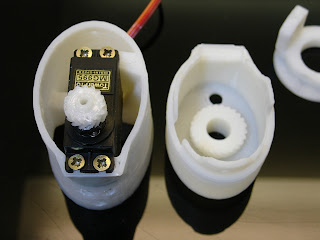
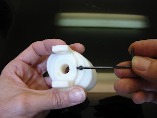
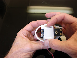
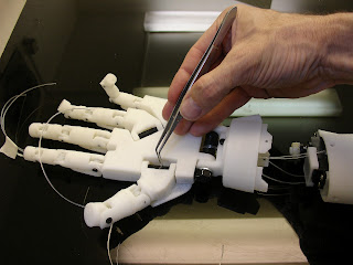
I finally updated all fingers hinges to make it much easier for assembly. If you have an acurate printer there shouldn't be anymore filling nor drilling. Although I have a quality reputated printer, holes shrink a little because of the overhang. I tried of making snap in parts like suggested Easton Lachapelle, but with the test I did, the strength of the traction exerced by the rods would disassemble the hinges.
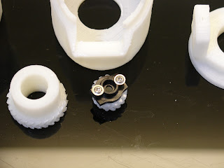
Anyway, I received the AS5040 Magnetic encoders ordered for the big servos. Soon time for electronics and adventure I really don't know much about...

Also trying to teach InMoov with voice recognition, and object detection. I'm far still from any good result. My camera is not even detected by the software myrobotlab, but the voice gives results. I tried to make him say something before he starts the action but I get really confused in some implementation for now. Those new softwares and concepts have to make their way in my brain first before to be applied to InMoov. 

Here is a little video:

There is someone that needs your interest at the moment, he has done a great job on producing a printable hand in one piece if I understand right. He plans on creating another version you can discover.
He has launched an indiegogo campaign here
http://anthromod.com/blog/?attachment_id=247

Article 16

$
0
0
Alright, I have fixed thumb4 problem to thumb5. I actually have no idea why it became bigger and couldn't fit wriargeV3 anymore. But I can't seem to upload it to thingiverse on the moment. It's been three days. I am located with a very poor internet connection at the moment. Hope this won't be long. Be patient, or if you are so desperate, go to thingiverse and send me your email, I will return you the STL.

InMoov by Brianhomer + Sugru

$
0
0
You should look at this video posted by brianhomer where he shows his final project. 
The project consist of using InMoov hand controlled through an Arduino with a power glove made by himself.
The demonstration with the can definitly shows that finger tips need to have silicone patchs in order to grab objects correctly. 
I have stumbled on a material that could be perfect for this use, I haven't tried it but it seems promising and easy to use. 
Google: sugru rubber
This material could be applied by hand directly on tips or even casted in a printed mold...
Anyway it seems a much easier solution then the one I used on my first hand.

Another thing about brianhomer project is the fact he used only one cable per finger which makes the return of fingers "uncertain", but he plans on building a second hand so I hope to see totally fonctionnal.

I contacted him to see if he would be kind enough to give me the Arduino sketch he came up for his power hand, it could save us time.

Article 14

$
0
0
Finally have been able to upload "thumb5" and "leftthumb5" on thingiverse.


By the way, I made a modification on "bolt_entretoise1" to "bolt_entretoise2" because the previous version had oversized bolts in length, I expected people to just cut them. But seeing pictures from the builders, I realized it confused somehow their assembly. I also added a fastening ring for the bolt that goes in the wrist.

Orange 3d printed hand

$
0
0
Why not in orange!
see  http://rymdstekel.blogspot.pt/
One recommendation I should suggest after having build a few hands, is to start lining the fishing rods from the servos to the finger tip. That way, when you make the knots at the tip, you can really pull and adjust the tension of the fishing rods. I found you can make more knots BEHIND the first knot to pull the rods at maximum. (I will make pictures of this technique to explain better soon)

Also the other day I discovered this http://robosavvy.com/forum/viewtopic.php?p=34865
Which is a way to convert InMoov STL files to CAD, I'm sure it will be handy for some of you.

Dilemna with "WristsmallV3" part

$
0
0
This will help, I am sure about it!
There is a new tab on the blog which contains Assembly Sketchs for a more comprehensive perception.
There is also other tabs that might interest you...


I want to clear a dilemna with "WristmallV3" part. Some of the builders might think during it's assembly to "WristlargeV3" that there is an error, because the fingers can go more further in open position than in closed one. This is because you need to fix the "topsurface". Once attached the fingers won't open too much.

Also the closing really shouldn't be too much, because once the finger tips are glued, you will get ringfinger stucked by majeure finger on full closing.  
If, after the complete assembly of those parts, it doesn't close enough to your taste, cut a little bit with a knife the blocks inside the palm, that stop the closing. 

Ringfinger should have a movement of about 15 degree and Littlefinger of about 20 degree while Thumb will normally have a 50 degree movement.
 

Power glove your robot hand

$
0
0
Feeling like actuating your robot hand with a PowerGlove?
Added InMoovPowerGlove (Thanks to brianhomer)on thingiverse.
This should get you going.
The zip contains a PDF diagram for connections and a sketch to upload on your Arduino board.

Inmoov by B.Stott

$
0
0
I have been in contact with someone since a while now, and I can tell you that person is really working on InMoov's hands. In fact, some suggestions came from him, for exemple the new brackets and the rotational bicep. 
Have a look at all his pictures, he did a great job. I am so delighted when I see others constructions, it really helps to make me go on with this project.
Thanks B.Stott
To see more of his work:  Here


Inmoov robot shoulder

$
0
0
Well, it's been a while since I haven't been able to print something. Holidays... I had been reviewing the concept of the shoulder. Not that my first system didn't work, but I wanted to get really more DOF. Sometimes I'm amazed of how many parts  I have to design and redesign under Blender before to finally be able to print them. Then, often, I have to redesign them again because of mistakes I discover once they are printed...
A box full of printed parts that are all for the trash.

Anyway, this should be something good, I am surprised of the strength it gives. Those HS-805BB servos are amazing.
This is what I plan on getting for the shoulder. Each cylinder has a servo motor and can rotate at 180°.
The cylinder contains a gear with a worm drive related to the servo.
I have extracted the potentiometer of the servo and fix it in the center of the cylinder.


 This is what I have printed so far, I had to print in green because I don't have anymore white ABS...It should arrive soon though. I really don't like this green... It doesn't look right on the robot, although I have nothing against bio colors.

Here it's mounted to the bicep, I had to redesign the mechanism system, and it isn't printed yet


Bicep for your Robot

$
0
0
This is it!
Today is the releasing day of the bicep, and the beginning of the shoulder.
Gee, since the last post I had again to redesign SO many parts it is unbelievable. First the shoulder isn't going to be like I thought because I encountered some direction problems, it didn't look human anymore... 
It was freaky! the shoulder was huge and too high which made InMoov like he had arms way too long.

Some pictures of the bicep, I have done many pictures of the whole building process, to make it easy to build. Actually it will be easier for you guys to build the bicep then the forarm.

I'm planning on making a step by step with pictures, just that, it's so much work.

Covers aren't ready yet, I am still working on the design, after all this is what gives the final look. The one you see on the pictures are just for show off, but it should be something close.

 Hope you enjoy it, because I do. When I see that arm moving by itself I feel like being in a sci-fi movie.

I need to make a little video to show how this works. As soon as I receive my white  ABS and I can print the rest of the covers.

Update 21/09/12: Assembly instructions uploaded in Tab "Assembly help" .
Update 01/10/12: Assembly sketchs uploaded in Tab "Assemblysketchs".


Bicep video of InMoov

$
0
0
Well, that took me a while to post. I just couldn't find the right moment for to make that video.
I should make a "making of", because for to achieve this one, I had to redo it five times . Between the phone that rings, the ground plug from the Arduino that disconnect, and me kicking the table and not knowing anymore what I am talking about...
You are lucky to finally see a video, I tell you.

This picture is for to show the latest covers of the bicep, looking from close at the picture you can see in the background the head of InMoov.

I work on the head when I get stucked in engineering some other parts, for example the shoulder has given me headaches, so from time to time I start studiying the head, it's eyes movments with the camera and other fun things.

 Update 07/10/12 covers are uploaded on Thingiverse.


InMoov at the Makerfaire

$
0
0
InMoov was presented at the Makerfaire of Pittsburgh by Brian. He had been working hard to get all his things ready for display. We can't see it on the picture but he also had a Rostock delta 3d printer he builded. Things didn't go like Brian wanted though that day, apparently some kids went aggressive on the 3D printed fingers... And on other presented things.
I have seen a video made that day by the local TV where he desperatly tempted to present InMoov, but that also didn't turn out like he wanted.
Anyway, I want to make a Special Thanks for his efforts that day.


InMoov's head and shoulders

$
0
0
Hey all,
Here is what I've got until now. I found some very talented people that are helping to developpe InMoov's brain. GroG is the guy that runs Myrobotlab and he has been helping to get InMoov listening to commands.
If you download his GUI you can do all kinds of interesting things with your robot. The neat part is that you can do all that with any Arduino board. The GUI still needs developpement but I have confidence to get to a point where I will understand how it works.
This a small video explaining some basic use of Myrobotlab.

And I have made a video with the last printed parts mounted on the robot.
Have a look it's getting to a point where it starts to look like something...
Hope you enjoy it!

Viewing all 75 articles
Browse latest View live